Wood-framed buildings use standard dimensional lumber as the load-carrying members, divided into two categories: posts, which are vertical elements holding up the structure’s weight and transferring that weight to the foundation, and beams, which support the weight between the poles.
Of the two, posts are much more easily understood, as they only have to be able to support a certain amount of weight.
On the other hand beams tend to deflect underweight; the more open space is between posts that the beam span has to span without support from the beam, the more they will deflect underweigh . But only so much deflection is allowe . The maximum limitation is calculated by taking the entire beam span without the support and dividing it by 360, with a maximum allowable deflection of 20mm.
In actuality, carpenters don’t do this calculation; they depend on deflection tables, which show how much different types, spans and dimensions of beam span tables without support tables made of wood will deflect ovadditionalent beam spans together.
Interpreting these tables cantle tricky for the layman, as we don’t always work with them. We need basic information on what material we can use for beam span tables without a support table and how long a beam span table can be used without any support.
Several other factors affect what this span is
The type of wood – Not all woods have the same density or grain structure; therefore, they don’t all support the same weight. For construction, we usually look at some conifer, like Douglas Fir, for which the characteristics are well known. However, different types of conifer will have different strength ratings, so it is important to know the type of wood and read only that type on the table.
Quality of the wood – We normally think of wood grading as affecting the appearance of a board, but those knots also affect the strength of the w od. In most cases, #2-grade lumber is used for framing; but if #1 or select lumber is used, it will span a larger distance.
The dimensions of the beam – All beams are made of 2″ thick lumber, although multiple pieces of that lumber may be used side-by-side to gain more strength. For beams or joists, the important dimension is the height of the beam, as that determines the strength. The wider it is, the farther the wood extends from the centerline, increasing its strength. The Floor and the Deflection
It is essential to consider the weight point loads that will be placed on the floor. This adds a layer of complication to the equation, giving us one more reason to work from a table rather than calculating the ideal size fl or. That weight live loads or load is broken into two parts:
Dead load – The weight of the building or its lf. For homes, the code requires that we use 10 psf (pounds per square foot) for the dead load if no ceiling is hung below those beams or joists and 20 psf if a ceiling is hung below it.
Live load – The weight of furniture, décor, and people in the h me. Building code specifies that a live load of 40 psf be used in living areas of a home and 30 psf be used in sleeping areas.
So, the most common loads we find in a typical home improvement call are:
Live load 40 psf, dead load 10 psf – Used for first-story floors and decks
Live load 30 psf, dead load 20 psf – Used for second-story floors
Live fiveoad 30 psf, dead load 5 psf – Use for roofs
Joists
The design of a home and the different uses of the joist span different areas of international residential building code can create a considerable variance in the size of the joists and beams used in a h me. However, most architects design homes to use the same size joists throughout or at least on every floor, simplifying the building process.
Having multiple joist sizes for the ground floor (for example) would make the design and building of the basement walls much more complicated, as it would be necessary to adjust the top of the walls to match the difference in floor joist height, just the roof raft rs. Those changes in ceiling joists’ height would need to be executed extremely accurately by a structural engineer and the foundation contractor, or the floor wouldn’t be level.
The following table provides maximum spans for floor joists and deck joists, by wood type, for a full joist span, with span tables for a live load of 40# and maximum beam span table lengths for a dead load of 0#. In all cases, it is assumed that #2-grade lumber is being used.
Joist Size
Spacing
Hem Fir
Spruce or Pine fir
Douglas Fir or Larch
Southern Yellow Pine
SYP Treated Decks
Cedar Decks
2×6
12” OC
10’
10’-3”
10’-9”
10’-9”
9’-11”
8’-10”
16” OC
9’-1”
9’-4”
9’-9”
9’-9”
9’
8’-1”
24” OC
7’-11”
8’-1”
8’-1”
8’-6”
7’-7”
7’
2×8
12” OC
13’-2”
13’-6”
14’-2”
14’-2”
13’-1”
11’-8”
16” OC
12’
12’-3”
12’-7”
12’-10”
11’-10”
10’-7”
24” OC
10’-2”
10’-3”
10’-3”
11’
9’-8”
9’-2”
2×10
12” OC
16’-10”
17’-3”
17’-9”
18’
16’-2”
14’-11”
16” OC
15’-2”
15’-5”
15’-5”
16’-1”
14’
13’-6”
24” OC
12’-5”
12’-7”
12’-7”
13’-1”
11’-5”
11’-3”
2×12
12” OC
20’-4”
20’-7”
20’-7”
21’-9”
19’-1”
18’-1”
16” OC
17’-7”
17’-10”
17’-10”
18’-10”
16’-6”
16’
24” OC
14’-4”
14’-7”
14’-7”
15’-5”
13’-6”
13’
This second table is for a live snow load of 30# and dead snow load of 10#, as a snow load would be needed for the second floor of a home, where the home design calls for the living space and the sleeping areas to be on only knee wall of the second floor.
Joist Size
Spacing
Hem Fir
Spruce or Pine fir
Douglas Fir or Larch
Southern Yellow Pine
2×6
12” OC
11’
11’-3”
11’-8”
10’-9”
16” OC
9’10”
9”-11”
10’-1”
9’-4”
24” OC
8’
8’-1”
8’-3”
7’-7”
2×8
12” OC
14’-4”
14’-7”
14’-9”
13’-8”
16” OC
12’-5”
12’-7”
12’-9”
11’-10”
24” OC
10’-2”
10’-3”
10’-5”
9’-8”
2×10
12” OC
17’-6”
17’-9”
18’
16’-2”
16” OC
15’-2”
15’-5”
15’-7”
14’
24” OC
12’-5”
12’-7”
12’-9”
11’-5”
2×12
12” OC
20’-4”
20’-7”
20’-11”
19’-1”
16” OC
17’-7”
17’-10”
18’-1”
16’-6”
24” OC
14’-4”
14’-7”
14’-9”
13’-6”
Please note that in cases where the span distances of the wood or other species or type are unknown, it is best to assume the weakest possible span tables for the lumber or wood species used for that application and use the maximum span shown for that lumber species or type.
Beams
Homes don’t have a lot of roof joists because of beams in them, with more floor joists rather than beams. What’s the difference with floor joists?
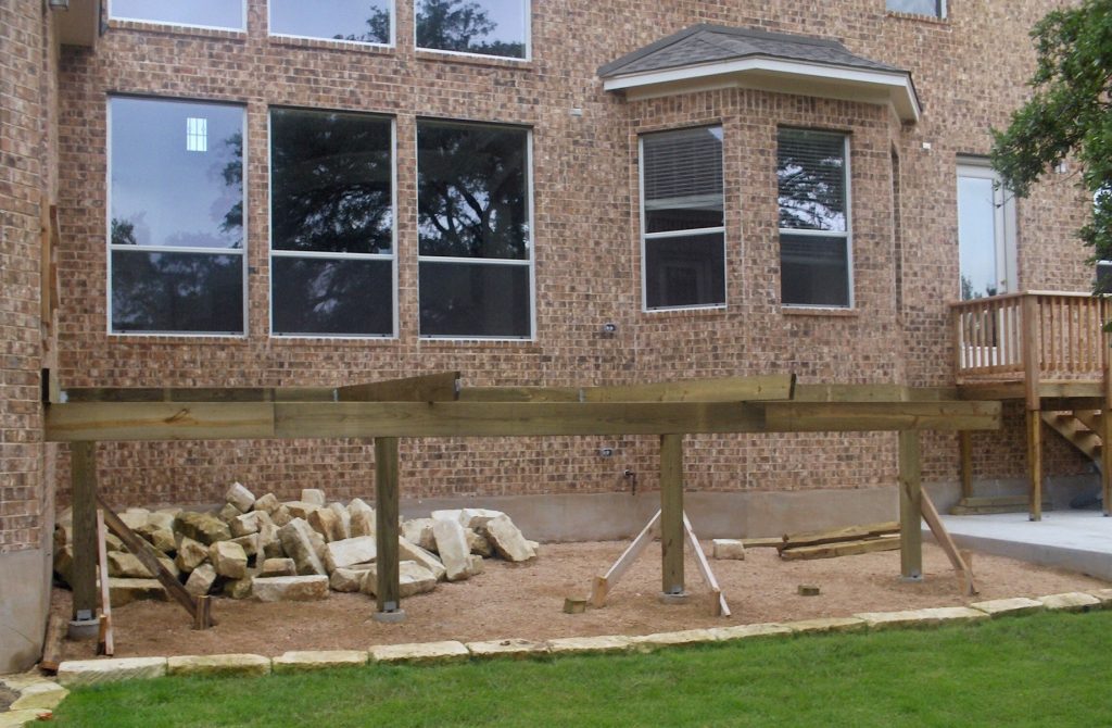
Beams are the major load-bearing horizontal elements, while joists are secondary ones. In a typical floor joist here, built over a crawlspace, there would be beams around the beams and down the center, allowing the joists to attach to the beams at the edges.
Typically, beams are made of multiple 2″”x 10″”s or 2″”x 12″”s, while the floor joists are single layers of the same size boards. Stacking a beam of multiple boards together increases their strength.
This beam is the critical weight-bearing part of the structural component of the home’s structure, as the beams must carry the weight of the other joist spans and rafters and all the weight of live loads they are carrying.
The weight of a single span of each beam supports those floor joists, and the weight of roof rafters load snow loads is figured into the maximum span for phrases.
In the table below, the same joist spans are also #1 and #2 grade lumber. Note “he” column for “Su” porte” J” ist Length.” T” refers to the floor joists attached o the beam. The longer the floor joists the beam supports, the shorter the distance between supports that the beam needs.
That distance is also affected by the size and number of pieces of wood used to make up the beam, as shown in the six columns t the right. Of course, in the case of a full basement, where the perimeter beams are sitting directly on the concrete basement walls, support’ and the floor joist’ and joist span amount are not an issue, as the beams have continuo s support. Hence, it is possible to have perimeter beams that are only two boards thick, while a center beam might need to be three or even four bo rds thick. This table is for a live load of 40 psf and a dead load of 10 psf.
Species
Joist Length
3-2×8 Built Up Beam Size
4-2×8
3-2×10
4-2×10
3-2×12
4-2×12 Built Up Beam Size
Douglas Fir
8’
9’-8”
11’-2”
11’-10”
13’-8”
13’-8”
15’-10”
10’
8’-8”
10’
10’-7”
12’-2”
12’-3”
14’-2”
12’
7’-11”
9’-1”
9’-8”
11’-2”
11’-2”
12’-11”
14’
7’-4”
8’-5”
8’-11”
10’-4”
10’-4”
11’-11”
16’
6’-10”
7’-11”
8’-4”
9’-8”
9’-8”
11’-2”
Hem-Fir
8’
10’-1”
11’-7”
12’-5”
14’-4”
14’-4”
16’-7”
10’
9’-1”
10’-5”
11’-1”
12’-9”
12’-10”
14’-10”
12’
8’3”
9’-7”
10’-1”
11’-8”
11’-9”
13’-7”
14’
7’-8”
8’-10”
9’-4”
10’-10”
10’-10”
12’-6”
16’
7’-2”
8’-3”
8’-9”
10’-1”
10’-2”
11’-9”
Spruce, Pine, Fir
8’
10’
11’
12’-10”
14’-1”
14’-11”
17’-2”
10’
9’-4”
10’-3”
11’-6”
13’-1’
13’-4”
15’-4”
12’
8’-7”
9’-8”
10’-6”
12’-1”
12’-2”
14’
14’
7’-11”
9’-2”
9’-8”
11’-2”
11’-3”
13’
16’
7’-5”
8’-7”
9’-1”
10’-6”
10’-6”
12’-2”
This second table is for a live load of 30 psf and a dead load of 20 psf.
Species
Joist Length
3-2×8 Built Up Beam Size
4-2×8
3-2×10
4-2×10
3-2×12
4-2×12 Built Up Beam Size
Douglas Fir
8’
7’-3”
8’-4”
8’-10“
10’-2”
10’-3”
11’-10”
10’
6’-6”
7’-6”
7’-11”
9’-2”
9’-2”
10’-7”
12’
5’-11”
6’-10”
7’-3”
8’-4”
8’-4”
9’-8”
14’
5’-6”
6’-4”
6’-8”
7’-9”
7’-9”
8’-11”
16’
5’-1”
5’-11”
6’-3”
7’-3”
7’-3”
8’-4”
Hem-Fir
8’
7’-7”
8’-9”
9’-3”
10’-8”
10’-9”
12’-5”
10’
6’-9”
7’-10“
8’-3”
9’-7”
9’-7”
11’-1”
12’
6’-2”
7’-2”
7’-7”
8’-9”
8’-9”
10’-2”
14’
5’-9”
6’-7”
7’
8’-1”
8’-2”
9’-5”
16’
5’-4”
6’-2”
6’-7”
7’-7”
7’-6”
8’-9”
Spruce, Pine, Fir
8’
7’-10”
9’-1”
9’-7”
11’-1”
11’-2”
12’-10”
10’
7’
8’-1”
8’-7”
9’-11”
10’
11’-6”
12’
6’-5”
7’-5”
7’-10”
9’-1”
9’-1”
10’-6”
14’
5’-11”
6’-10”
7’-3”
8’-5”
8’-5”
9’-9”
16’
5’-7”
6’-5“
6’-9”
7’-10”
7’-11”
9’-9”
The beam the various span ranges the beam can span.
The beam span lengths listed in the isn’t above probably isn’t going to be sufficiently long for the structure is eing built.
The idea is that supporting columns or posts would need to be installed with that beam span calculator frequency so that the beam can span more distances and longer spans the beam can span to ensure that the beams have sufficient support.
The next question is how to build those beams stick, buil hip roofs. They will be built out of standard #2-“dimensional lumber, 2” thick “, using a width that”will be adequate to the wind load and support the weight of the hip roof.
As mentioned, using the same-sized lumber for the beams and joists normal. To gain extra strength, additional pi es of grade or wood species are laminated together, making a thicker beam.
Buying this lumber long enough to make a three-ply beam out of only three pieces is often i possible. That lumber is going to have to be spliced together omeplace. Care and planning must be used in determining where to get construction timber to make those splices so that the beam will have the necessary strength.
Assuming a three-ply beam, the ideal position for the splices on the middle ply is directly over the supp rt posts. That will make the middle ply function essentially as if it is one continu us piece. But the other two plies cannot be joined at the s me place. The joints will need to be staggered for those pieces to maintain the overall structural integrity of the beam.
They should be a minimum of four feet away from the joints in the center ply and four feet away from e ch other. If possible, it is even better if the joints in those plies are between different pairs of columns, so there is no place along the length of the entire beam where two seams are between any pair of supporting posts.
To connect the boards, use a combination of different grades of construction adhesive screws or “ails. Spiral nai”s are preferred. All screws should “e #10 at least 3” long, and nails should be 10d or longer.
Before nailing, liberally apply construction adhesive between e boards. “hen nails them i” in a zigzag pattern, spacing the nails”no more than 16” apart.
Be sure to double-nail at both ends of the deck beam on every board so that there are nails in the top and bottom edges of the board.
The finished beam will probably be quite heavy, and some help will be required to set it in place.
Related Posts:
Best Plywood Thickness for Roofing (16" & 24" Span Guide) by Admin June 16, 2026 DIY Selecting an incorrect roof sheathing thickness is an expensive, high-risk error. Thin sheathing sags under heavy structural loads, violates local building codes, and strips out…


")
")