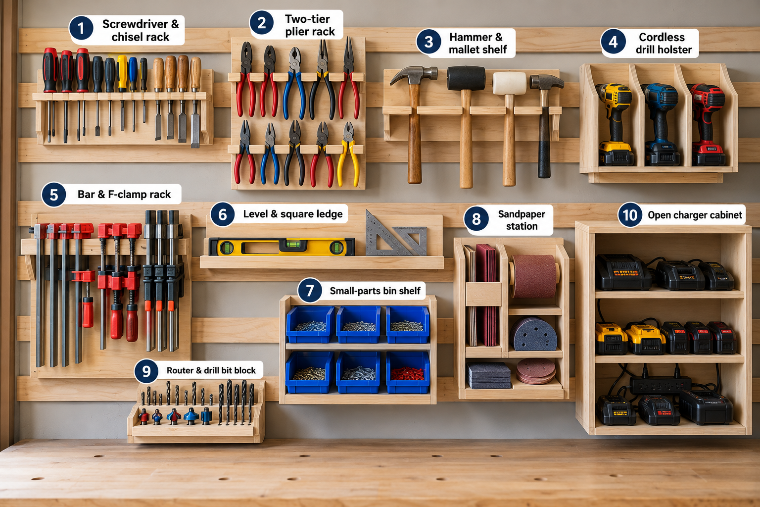
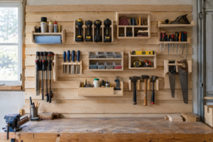
All 10 French cleat tool holders on this page use the same cleat: 3/4″ plywood, 3-1/2″ wide, with a 45° bevel, glued flush to the top of a 3/4″ plywood back. Build every holder to that one profile and any holder hangs on any row of your wall. This page gives the dimensions and cut list for each design, plus the spacer test-fit, a plywood budget, wall-mounting steps, a pre-use check, and the cases where a cleat holder is the wrong choice.
If your wall rows aren’t up yet, start with our French cleat wall guide. This page picks up at the step where that guide ends: building the holders.
Quick answer
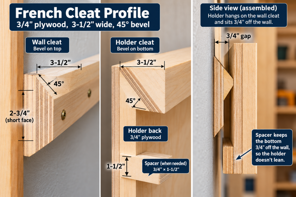
Cleat: 3/4″ plywood, 3-1/2″ wide, 45° bevel. Use the same profile on the wall and on every holder.
Holder back: 3/4″ plywood, with the holder cleat flush with its top edge.
Spacer: 3/4″ × 1-1/2″, only where the bottom of the back would otherwise bear on bare wall. Test-fit to find out.
Wall cleats: two 3″ structural screws into every stud they cross.
Lift clearance: leave at least 1-1/2″ above each holder.
French Cleat Tool Holders at a Glance
“Sticks out” is the distance from the wall to the front of the holder. The plywood figure is the net 3/4″ area of the parts, before kerf and waste.
#
Holder
Holds
W × H
Sticks out
3/4″ ply (net)
Load
Skill
1
Screwdriver & chisel rack
11 drivers or 8 chisels
18″ × 6″
5″
1.9 sq ft
Light
Easy
2
Two-tier plier rack
Pliers on 2 rails
16″ × 17″
3-3/4″
2.9 sq ft
Light
Easy
3
Hammer & mallet shelf
4 hammers
16″ × 6″
5-1/2″
1.8 sq ft
Medium
Easy
4
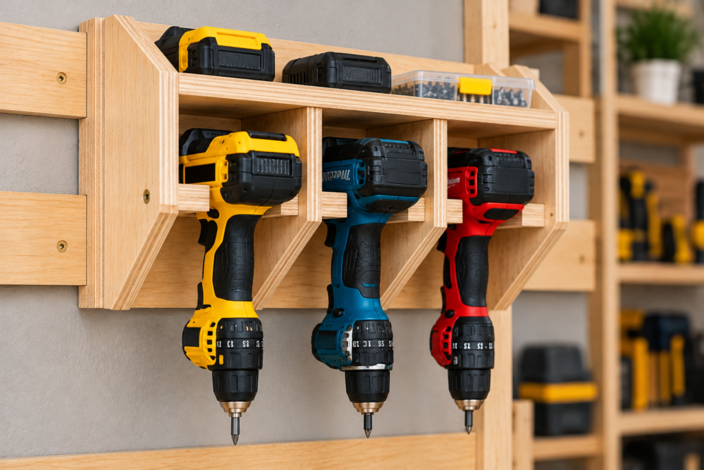
Cordless drill holster
3 drills/drivers
24″ × 10″
7-1/2″
3.9 sq ft
Medium
Moderate
5
Bar & F-clamp rack
8 clamps
24″ × 9″
6-1/2″
3.4 sq ft
Heavy
Moderate
6
Level & square ledge
Levels, squares
36″ × 5″
4-3/4″
3.0 sq ft
Light
Easy
7
Small-parts bin shelf
Stacking bins
24″ × 10″
7-1/2″
4.6 sq ft
Medium
Easy
8
Sandpaper station
Sheets, rolls, blocks
14″ × 14″
5-3/4″
2.0 sq ft + 1/2″ ply
Light
Easy
9
Router & drill bit block
19 bits
16″ × 6″
5″
1.9 sq ft
Light–Medium
Easy
10
Open charger cabinet
Chargers, batteries
24″ × 25″
9-1/4″
7.9 sq ft + 1/2″ ply
Heavy
Moderate
The load classes compare the holders with each other. They are not weight ratings.
The One Cleat Profile Behind All 10 Designs
Most cleat walls fail slowly. One holder gets a 3″ cleat, another gets 4″, a spacer comes from different stock, and within a year half the holders lean. Settle on one profile before you cut anything.
Cleat Geometry
Part
Stock
Size (width × length)
Orientation
Wall cleat
3/4″ plywood
3-1/2″ × run length
Short face against the wall, bevel on top. The front edge is the high point.
Holder cleat (HC)
3/4″ plywood
3-1/2″ × holder width
Short face glued to the holder back, bevel on the bottom, low point toward the wall. Its top is flush with the top of the back.
Spacer (SP)
Same sheet as the cleats
1-1/2″ × holder width
Bottom of the holder back, only if the test-fit calls for it
The 3-1/2″ is the long face. The short face is 3-1/2″ minus the sheet’s actual thickness: about 2-3/4″ on a true 3/4″ sheet, and a little more on 18mm Baltic birch.
How to Cut the Cleats
Rip 3-1/2″ strips with the blade at 90°.
Tilt the blade to 45° and bevel one edge. Set the fence so the cut removes only the corner and the 3-1/2″ face stays full width.
This two-cut method doesn’t depend on kerf width or sheet thickness. Cut one pair from scrap first, check that the two pieces seat together without rocking, and only then cut the batch.
Cut spacers from the same sheet as the cleats. “3/4-inch” Baltic birch is 18mm, or about 0.70″ according to our European and Baltic birch plywood guide. A spacer cut from thicker stock makes the holder lean.
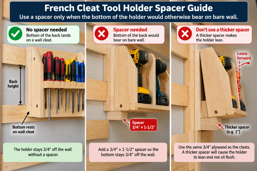
The Spacer Rule
A hung holder’s back sits 3/4″ off the wall at the top, where the two cleats lock together. The bottom of the back has to sit 3/4″ out as well, or the holder leans. Where the bottom lands on your wall decides whether you need a spacer.
Where the bottom of the back lands
What to do
On the face of a wall cleat (the one it hangs on or one below)
No spacer. That cleat already holds the bottom 3/4″ out.
On bare wall
Add the 3/4″ × 1-1/2″ spacer
Partly on a cleat and partly on bare wall
Change the back height by about an inch so it lands cleanly on one or the other
Test-fit every holder before you add a spacer:
Build the holder without a spacer and hang it on its row.
Look at the bottom edge of the back.
If the bottom leans in and touches bare wall, add the spacer.
If the bottom bears flat on a cleat face and the back hangs plumb, leave the spacer off.
Check with a square or level against the back either way.
Holders with short backs, around 6″ tall like designs 1, 3, 6 and 9, usually rest on the face of the cleat they hang on and need no spacer. Taller holders depend on your row spacing, so test-fit each one.
10 French Cleat Tool Holder Designs
These are design plans with calculated dimensions, not shop-tested builds. Dry-fit each holder and test-cut slots and holes in scrap before cutting good stock.
How to read the cut lists: Size is width × length in inches. Thickness is in the Material column. Gussets are listed as the square you cut them from: one square cut corner to corner gives two triangles. The HC and SP lengths match the holder width.
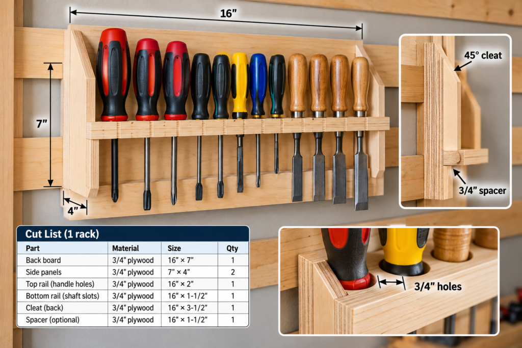
1. Screwdriver and Chisel Rack
A drilled shelf. Handles rest on top and shafts drop through.
Part
Qty
Material
Size (W × L)
Back
1
3/4″ ply
6 × 18
Shelf
1
3/4″ ply
3-1/2 × 18
Gusset square
1
3/4″ ply
3-1/2 × 3-1/2
HC
1
3/4″ ply
3-1/2 × 18
SP
Only if the test-fit calls for it
3/4″ ply
1-1/2 × 18
Drill pattern:
Screwdriver version: 11 holes at 5/8″ on 1-1/2″ centers. The first hole is 1-1/2″ from the end, and the row runs 1-3/4″ in from the front edge. That size clears the shafts of most standard drivers, but measure your largest shaft first.
Chisel version: 8 holes at 1-1/8″ on 2″ centers, starting 2″ from the end, for blades up to 1″ wide.
Keep each end hole at least 1-1/2″ from the end so it clears the gussets. If you want tools to slide out forward, cut a 5/16″ slot from each hole to the front edge, as our tools-on-the-wall guide suggests.
2. Two-Tier Plier Rack
Pliers hang open over a rail held off the back, with one handle in front and one behind.
Part
Qty
Material
Size (W × L)
Back
1
3/4″ ply
16 × 17
Rails
2
3/4″ ply or hardwood
1-1/4 × 16
Standoff block pieces
8
3/4″ ply, glued in pairs into 4 blocks 1-1/2″ thick
1-1/4 × 1-1/2
HC
1
3/4″ ply
3-1/2 × 16
SP
Only if the test-fit calls for it
3/4″ ply
1-1/2 × 16
Mount the top of the upper rail 2″ below the top of the back and the top of the lower rail 9″ below it. Screw the blocks to the back and the rails to the blocks. Expect about 6–8 pliers per rail.
3. Hammer and Mallet Shelf
The heads rest on the shelf and the handles hang through open slots.
Part
Qty
Material
Size (W × L)
Back
1
3/4″ ply
6 × 16
Shelf
1
3/4″ ply
4 × 16
Gusset square
1
3/4″ ply
4 × 4
HC
1
3/4″ ply
3-1/2 × 16
SP
Only if the test-fit calls for it
3/4″ ply
1-1/2 × 16
Slots: 4 slots, each 1-3/8″ wide × 3″ deep from the front edge, centered at 2″, 6″, 10″ and 14″. Bore the end of each slot with a 1-3/8″ Forstner bit, then cut to it with a jigsaw. Measure your thickest handle first.
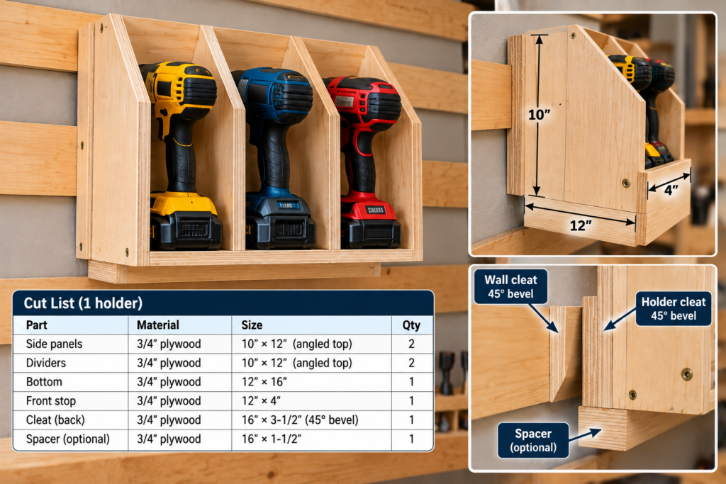
4. Cordless Drill Holster Shelf
Each drill hangs handle-down through a slot, with the motor body resting on the shelf.
Part
Qty
Material
Size (W × L)
Back
1
3/4″ ply
10 × 24
Shelf
1
3/4″ ply
6 × 24
Gusset squares
2
3/4″ ply
5-1/2 × 5-1/2
HC
1
3/4″ ply
3-1/2 × 24
SP
Only if the test-fit calls for it
3/4″ ply
1-1/2 × 24
Slots: 3 slots, each 2-1/4″ wide × 4-1/2″ deep, centered at 4″, 12″ and 20″. Place gussets at both ends and at 8″ and 16″. Measure your drill grips before cutting. Keep chargers on design #10. For a full charging-wall layout, see our cordless drill charging station plans.
5. Bar and F-Clamp Rack
Clamp bars drop into slots and the heads rest on the arm. This is the heaviest holder per foot, so hang it on a low row.
Part
Qty
Material
Size (W × L)
Back
1
3/4″ ply
9 × 24
Arm
1
3/4″ ply
5 × 24
Gusset squares
2
3/4″ ply
4-1/2 × 4-1/2 (use 3 triangles)
HC
1
3/4″ ply
3-1/2 × 24
SP
Only if the test-fit calls for it
3/4″ ply
1-1/2 × 24
Slots: each slot’s width is your measured bar thickness plus 1/64″. Make them 3-1/2″ deep, on 2-1/2″ centers at 2-1/2″, 5″, 7-1/2″, 10″, 14″, 16-1/2″, 19″ and 21-1/2″. Position 12″ is left open for the center gusset. The clearance and the 1/8″–1/4″ gap between clamps follow our tools-on-the-wall guide. Widen the centers if a clamp head is wider than 2-1/4″.
6. Level, Square and Straightedge Ledge
A lipped ledge for levels, with two pegs for framing squares.
Part
Qty
Material
Size (W × L)
Back
1
3/4″ ply
5 × 36
Ledge
1
3/4″ ply
2-1/2 × 36
Lip
1
3/4″ ply
1-1/4 × 36 (stands 1/2″ above the ledge)
Pegs
2
1/2″-diameter hardwood dowel
3-1/2 long
HC
1
3/4″ ply
3-1/2 × 36
SP
Only if the test-fit calls for it
3/4″ ply
1-1/2 × 36
Fasten the ledge flush with the bottom of the back using glue and three screws. Drill stopped peg holes: 1/2″ diameter, 5/8″ deep, 2″ down from the top, at 8″ and 28″ from the left end. A framing square hangs by its inside corner. Keep this holder away from doorways, because long levels overhang it.
7. Small-Parts Bin Shelf
An open box for stacking bins, with a front lip.
Part
Qty
Material
Size (W × L)
Back
1
3/4″ ply
10 × 24
Sides
2
3/4″ ply
6 × 10
Bottom
1
3/4″ ply
6 × 22-1/2
Front lip
1
3/4″ ply
2 × 22-1/2
HC
1
3/4″ ply
3-1/2 × 24
SP
Only if the test-fit calls for it
3/4″ ply
1-1/2 × 24
The sides butt against the front face of the back. The bottom fits between the sides, and the lip sits on the bottom’s front edge. Measure your bins first. Full bins of fasteners are heavy, so hang this one waist-high or lower.
8. Sandpaper Station
A pocket for sheets and two angled pegs for abrasive rolls and sanding blocks.
Part
Qty
Material
Size (W × L)
Back
1
3/4″ ply
14 × 14
Pocket front
1
1/2″ ply
6 × 14
Pocket sides
2
3/4″ ply
1-1/2 × 6
Pocket bottom
1
3/4″ ply
1-1/2 × 12-1/2
Pegs
2
3/4″-diameter hardwood dowel
5 long
HC
1
3/4″ ply
3-1/2 × 14
SP
Only if the test-fit calls for it
3/4″ ply
1-1/2 × 14
The pocket’s interior is 12-1/2″ wide × 1-1/2″ deep, so 9 × 11 sheets stand on their long edge. Drill the peg holes through the back at a 10° upward angle, 5″ down from the top and 3-1/2″ in from each side. Glue the pegs and cut them flush at the back.
A laminated block with stopped holes, so bits stand upright.
Part
Qty
Material
Size (W × L)
Back
1
3/4″ ply
6 × 16
Block layers
2
3/4″ ply, glued face to face (1-1/2″ thick)
3-1/2 × 16
Gusset square
1
3/4″ ply
3-1/2 × 3-1/2
HC
1
3/4″ ply
3-1/2 × 16
SP
Only if the test-fit calls for it
3/4″ ply
1-1/2 × 16
Drill pattern:
Front row: 12 holes at 17/64″ for 1/4″ shanks, on 1-1/4″ centers, 1″ from the front edge.
Back row: 7 holes at 17/32″ for 1/2″ shanks, on 2″ centers, 1″ from the back edge.
Drill all holes 1-1/4″ deep and stop there.
The one-size-over hole follows our tools-on-the-wall guide. Void-free plywood matters here, because a core void under a hole leaves the bit leaning.
10. Open Charger and Battery Cabinet
This is the heavy holder in the set. It has an open front for charger ventilation, and an internal mounting rail so the hanging screws bite into the face of the plywood rather than into an edge.
Part
Qty
Material
Size (W × L)
Sides
2
3/4″ ply
8 × 25
Top and bottom
2
3/4″ ply
8 × 22-1/2
Shelf
1
3/4″ ply
7-3/4 × 22-1/2
Mounting rail
1
3/4″ ply
3-1/2 × 22-1/2
Back
1
1/2″ ply
24 × 25
HC
1
3/4″ ply
3-1/2 × 24
SP
Only if the test-fit calls for it
3/4″ ply
1-1/2 × 24
Construction plan. Dry-fit everything before you glue.
Carcass. Glue and screw the top and bottom between the sides, and set the shelf at about 12″.
Mounting rail. Fit the rail between the sides, tight under the top panel and flush with the back edges of the sides. Glue it to the underside of the top, and fasten it through each side with two pilot-drilled #8 × 1-1/2″ screws.
Back. Glue the 1/2″ back to the rear edges of the carcass and the rail, and screw it every 6″.
Holder cleat. Glue the holder cleat to the rear face of the back with its top flush with the top of the back. It overlaps the rail through a band about 3/4″ to 3-1/2″ below the top. Screw through that band from both sides, staggered, every 3″.
Choose screw length from your actual stock. Measure the real thickness of rail + back + cleat. With nominal stock that’s 3/4″ + 1/2″ + 3/4″ = 2″. Pick a screw length that stops at least 1/4″ short of the far face, so no tip reaches the wall side of the cleat. With nominal stock that works out to about 1-3/4″. Thinner metric plywood needs a shorter screw.
Spacer. If the test-fit calls for one, glue it to the rear face of the back at the bottom and screw it from inside, again choosing a length that stops short of the wall face.
Mount chargers following each charger maker’s instructions. Route cords out through a 1-1/2″ hole in a side panel. Don’t add doors, and don’t daisy-chain power strips. Hang the cabinet empty, then load it.
Plywood Budget: How Much to Buy
💸 Cost difference: the net part areas leave out saw kerf, edge trim, defects and test cuts. Treat the figures below as planning allowances. Your own cutting layout decides the final count.
What you’re building
Net 3/4″ area
Plan to buy
Designs 1–9
about 26 sq ft (a 4×8 sheet is 32)
2 sheets of 3/4″. One sheet is too tight once you allow for kerf and waste.
Designs 1–9 + four 8-foot wall rows
about 35 sq ft
2 sheets of 3/4″
All 10 + four 8-foot wall rows
about 43 sq ft
3 sheets of 3/4″
1/2″ parts (#8 pocket front, #10 back)
about 4.8 sq ft
One 2×4 panel of 1/2″
That makes the grade upgrade a two- or three-sheet decision. Better plywood pays off in the cleats, the spacers, the bit block and the slotted shelves, where core voids show up at holes and bevels. Backs and sides can be a cheaper grade. Check local pricing for both.
Mounting Guidance: Wall Cleats That Actually Hold
✅ Find studs, then confirm them. Wall studs in houses are generally 16″ or 24″ on center, the spacings in IRC Table R602.3(5). Confirm each stud with a small test hole where a holder will cover it.
✅ Cross several studs. A wall cleat fastened to one stud can pivot.
✅ Use structural screws, not drywall screws. Two 3″ structural screws per stud through 3/4″ plywood and 1/2″ drywall leave about 1-3/4″ of thread in the stud. Check the screw maker’s minimum penetration.
✅ Predrill per the screw maker. If you use #10 wood screws instead, our pilot hole chart lists a 7/64″ pilot into softwood studs and a 3/16″ clearance hole through the cleat.
✅ Countersink the heads flush. Holder backs rest against the wall cleat’s front face, so a proud head makes a holder rock.
✅ Keep screws out of the bevel. Drive them at least 1″ below the top point.
✅ Level the first row, then gauge the rest. Cut spacer blocks equal to your row spacing minus 3-1/2″, sit each new row on them, and still check each row with a level.
✅ Masonry: use anchors rated for the substrate, or fasten furring to the masonry first and mount the cleats to that. Our hanging wall cabinets guide covers this approach.
Check Every Holder Before You Use It
🧪 Real test (run it yourself): this check finds build and installation mistakes, such as a cleat that isn’t fully seated, a spacer in the wrong place, loose screws or too little lift clearance. It does not tell you how much a holder can safely carry, and passing it is not a load rating. Don’t keep adding weight to find the limit.
Empty push check. Hang the empty holder and press down on its front edge with a flat palm. The holder cleat should stay seated, with no gap at the wall.
Normal load, overnight. Load it with the tools it was built for and leave it 24 hours. Then confirm it still hangs plumb and no screw heads have backed out.
Lift-off check. Lift it straight up. It should come off cleanly. If it binds, add clearance. Re-hang it and confirm it doesn’t rock.
If any step fails, fix the build before you load the holder again.
When a French Cleat Holder Is the Wrong Choice
Heavy or overhead loads. Anything whose fall could injure someone needs a mount designed and rated for that load. Our French cleat wall guide makes the same point.
Steel studs. Wood screws don’t hold in light-gauge steel. Use fasteners rated for steel framing.
Drywall alone. Anchors can stay tight while the drywall around them tears out.
Walls that vibrate. Next to a table saw, jointer or planer, lock holders with one #8 screw through the holder cleat into the wall cleat.
⚠️ Warning, kids in the shop: a child can lift a holder full of chisels off the wall as easily as you can. Keep sharp-tool holders high and screw-locked, or lock the room.
Best Materials and Tools for French Cleat Tool Holders
❌ Adding a spacer where the back already rests on a cleat. The bottom kicks out 3/4″ and tools slide toward the front edge. Test-fit first.
❌ Cutting spacers from different stock. An 18mm cleat next to a full 3/4″ spacer makes every holder lean slightly.
❌ Leaving screw heads proud on the wall cleat. Holders rock and work loose over time.
❌ Screwing a heavy holder’s cleat into plywood edge grain. Edge screws in plywood split and pull out more readily than face screws. Use a face-grain joint like the mounting rail in design #10.
❌ Leaving no lift clearance. A holder tucked tight under the next one can’t come off the wall.
😬 Regret: building every holder before setting the row spacing. Whether a holder takes a spacer depends on where its bottom lands, so put the rows up first and test-fit as you go.
What size should a French cleat be for tool holders? 3/4″ plywood, 3-1/2″ wide, with a 45° bevel works for everything from a screwdriver rack to a charger cabinet. Using one size on every holder matters more than the exact size.
Can I use 1/2″ plywood for French cleat holders? For the backs of light holders, yes. Keep the cleats and spacers 3/4″ and cut from one sheet, so every holder sits the same distance off the wall.
Does the bevel have to be exactly 45 degrees? 45° is the common choice. What matters most is cutting the wall and holder cleats at the same setting so they seat fully.
Do French cleat holders need a bottom spacer? Only when the bottom of the back would otherwise bear on bare wall. If it rests on a cleat face, a spacer makes the holder lean. Hang the holder without one and look.
How do I stop holders from lifting off the wall? Drive one #8 screw through the holder cleat into the wall cleat. Do this near vibrating machines and on any holder with sharp tools within a child’s reach.
Bottom Line
Cut one cleat profile, 3/4″ × 3-1/2″ at 45°, and test-cut a pair before you cut the batch. Put the rows up first, test-fit each holder to decide on a spacer, and check every holder before loading it. That check catches build mistakes but doesn’t rate a holder for any weight.
How to Build a French Cleat Wall: Complete DIY Guide by Admin September 15, 2026 Installing A French cleat wall is one of the simplest ways to organize tools without locking yourself into a permanent layout. Instead of attaching every shelf, rack and…