Wooden gears and sprockets have been in use for millennia. While the actual history of early gears is rather unclear, they were first written about by the Greek mathematician Hero of Alexandria in 50 AD. But there is evidence that they were used by the Greeks in the third century BC, having been invented by Archimedes. There is other evidence pointing to the Chinese as the actual inventors, who may have used gears in chariots centuries before that. Of course, like many ancient inventions, neither of these preclude the other, as there were many inventions that came about in different places at different times. Due to the lack of reliable communications and commercialization, inventions didn’t spread as rapidly as they do today.
While some of those early gears may have been made of metal, there were also a lot of gears made of wood. One of the more prolific uses of wood gears was in conjunction with water wheels. We normally only see the wheel itself, but the wheel rotates around an axle (a whole tree trunk), that goes into the lower room of the mill, where it is run through a right-angle gear drive, and possibly other gears to increase the speed, allowing the power developed to be sent upstairs into the working area of the mill.
Many early clocks used wood gears as well, although few examples remain to us today. The constant wear on the wood demonstrated the need to switch over to metal, providing more accuracy and durability.
Today, wood gears are more of a novelty than anything else. Woodworkers People make wood gears more for decorative purposes, than anything else. That doesn’t mean that they have to be limited to that use though, as they can be quite useful for those of us who make our own jigs and power tools. There exists a wide range of ways that wood gears can be used for making that tooling, such as in moving a sliding table. It all depends on the woodworker’s imagination.
Many people who make these gears cheat a bit, just like the companies who manufacture wood gears for sale. By “cheat” I’m referring to making them via laser cutting. While that works well and produces clean gears easily, it takes something enjoyable and challenging out of the process. The idea of making wood gears isn’t just to get the finished gears, but also to enjoy the road from here to there.
Let’s Talk Gears
There’s a fair amount of misunderstanding about gears that we should probably clear up, before getting into making any gears. To start with, the terms “gear” and “sprocket” are often used interchangeably, even though they aren’t the same thing. The basic difference is that gears are designed to mesh with other gears, while sprockets are designed to be used with chains or toothed belts.
The second thing we need to understand is that for any set of gears to work requires all the teeth of the gear to be the same size and shape. It doesn’t matter if we’re talking about spur gears, internal gears, helical gears or bevel gears. In each case, the teeth on every gear used in the set have to match.
One exception is where two gears are mounted on the same shaft, turning together. In that case, one gear can be toothed to work with one set and the other can have a different size and/or type of tooth to work with another set. This is actually quite common, especially when using gears and sprockets together.
The other exception that exists with wood gears is something specific to water wheels. The water wheel’s axle will often have a crown wheel attached to the other end. This is a round wheel, with dowels sticking out from it, around the perimeter, much like candles on a birthday cake. These “teeth” on the crown wheel interface with a lantern pinion, a barrel-shaped device, with wheels on either end, connected by a series of dowels. The crown wheel and lantern pinion are used mostly because they don’t require high precision to make. When mounted, the lantern pinion sits so that the spokes of the crown wheel go between its dowels, so that as the water wheel turns, the force developed is sent at 90 degrees up through the floor of the mill.
In the case of wood gears, we can’t make the teeth too small, as they lose strength. I’m not sure if anyone knows the actual bottom end of tooth size, but it would depend at least in part on the material used. If a circle were fabricated out of sections of maple, so that there was end grain sticking out all around the perimeter of the circle, it would have the strength to cut smaller teeth, but for most applications, it is best not to go smaller than 10mm.
Material selection is important. The need for all the teeth to be strong pretty much limits the manufacture of wood gears to some sort of plywood. But not just any plywood will work. Softwood construction plywood has too coarse a grain with too many voids for use in making gears. It’s much better to use something with a fine wood grain and no voids.
How Gears are Used
Gears are capable of doing three basic things: changing the speed of rotation, changing how much force is transmitted, and changing the direction of rotation. Changing direction of rotation doesn’t really have any impact on the other two, but changing either the speed affects the amount of available force.
First of all, the number of teeth that the two gears have affects the output speed. If there is a large input gear, with a small output gear, the speed will increase, as each revolution of the input gear will equal several revolutions of the output gear. In contrast to that, if a small input gear is used with a large output gear, then it will take several revolutions of the input gear to equal one revolution of the output gear, slowing the speed. To calculate exactly how much of a difference, count the number of teeth in each gear and use that as a ratio.
That ratio will also allow calculating how the change in speed affects the change in available force. If the ratio is 10:1, meaning that an input speed of 10 gives an output speed of 1 (ten times as many teeth on the input gear as on the output gear), the force provided will be 10 times the input force.
This is commonly used with gear motors, taking the natural speed of a motor, which is either 1800 RPM or 3600 RPM for an AC motor and dropping that speed down to what is needed. So, taking that 1800 RPM and dropping it down to 180 RPM will allow a 1/10 HP motor to do work that would otherwise require a 1 HP motor at 1800 RPM.
It All Starts with the Design
The number of teeth each gear has and not the size of the gear is the starting point for the design of any gear train. In some cases, the size of the teeth is determined by the need to shoehorn the gear into a specific amount of space; but that’s assuming the luxury of working with hardened steel gears, which can carry much more load than wood gears can. Still, the idea fits, as wood gears which need to carry a lot of load would need to either be made of thicker plywood, perhaps laminating several sheets together or made larger so as to have larger teeth (or a combination of the two).
For our sake we’re going to assume ½” gear tooth size, as that’s a common, easily available size that just about any woodworker will have in their kit. If we need a gear with 10 teeth in it, we really need to calculate based on 20 teeth, as the space between the teeth needs to be the same size as the teeth themselves. So, 20 times 0.5” gives us a circumference around the circle of 10”. To find out what diameter that is, we divide the 10” by Pi, Π, which is 3.14 and we get 3.18”. So we need to draw a circle with a 3.18” diameter or a 1.59” radius.
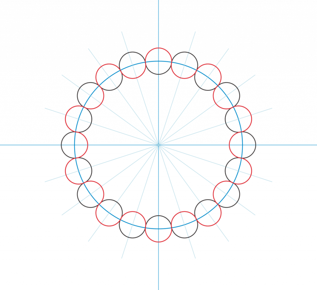
After drawing that circle with a compass or on the computer, we need to draw our 20 – ½” circles around the circle, so that each of them is touching its neighbor. Let’s step through this process:
If using a compass:
Start by drawing two lines, perpendicular to each other, in the center of a piece of paper (best to use cover stock).
Sharpen the compass’ lead and set the compass to 1.59”
Place the compass point at the intersection of the two lines and scribe a circle around them.
Reset the compass to 0.25” (this might require a rather small compass)
Pick a point on the circumference of the circle and set the compass point on it. Then scribe a circle around that point.
Move the compass so that the lead of the compass is at the intersection of the large circle and the small one that has just been drawn. Then set the compass point on the 3.18” circle, wherever it naturally falls.
Scribe another ½” circle.
Continue around the circle in this manner, until the 20th circle meets back up with the edge of the first.
Open up any vector drawing program, and make two perpendicular lines on a blank page.
Make a 3.18” diameter circle, centered on those perpendicular lines.
Since we need 20 – ½” diameter circles, we’ll divide 360 degrees by 20, to get 18 degrees.
Make a series of lines, each of which has one end on the center of the crosshairs and the other end rotated 18 degrees offset from its neighbor. Most vector drawing programs allow you to type the value in, providing very precise placement of those lines.
Make a ½” diameter circle.
Move that circle so that the center of it is on the intersection of the 3.18” diameter circle and any of the lines radiating out from the center.
Copy the ½” circle and move the copy so that it is centered on another intersection.
Continue this way until all 20 of the circles have been drawn.
Print out the drawing, preferably on cover stock.
Gear pattern 1
The diagram above was made in an older version of Corel Draw, following the directions written above. I have also made an almost identical diagram in Autosketch, just to prove it can be done. The diagram below has all extra lines removed, making it easier to see how the gear will look when cut out.
Gear outline
This sort of gear will work well, when used on the flat, along with other gears, to increase or reduce speed. However, round teeth like this are not the best design when having the gears perpendicular to each other, as would be needed to change the direction of the movement.
There is an excellent tool available online, which will design gears. All that’s needed is to insert the number of teeth in each gear, along with the tooth spacing and a few other pieces of information. The application makes the design in real time, allowing you to print out a full-sized pattern. This app is available at WoodGears.
Online gear design app
Making the Simplest Form of Wooden Gear
There are ways of cheating to get a good wood gear, without having to go through all the trouble of cutting out all the teeth of a gear. While this is not really something that any of us would want to do for decorative gears, it is something that can be useful for shop equipment.
The secret is to use a serpentine belt which is designed for use with a sprocket. These belts have ribs running across the width of the belt, rather than ridges running down their length. The ribs work rather well as gear teeth, in applications where there isn’t a lot of load on the gear. Proper spacing of the gears is necessary, so that the teeth make good contact, without crushing the rubber and causing excessive drag on the gear train.
To make this sort of gear, start by cutting the belt to provide the right number of teeth. Make sure that they are all full teeth, as well as having a full valley at one end. Measure how long this section of belt is, and divide that by Pi to determine the diameter of the wood disc needed to mount it to.
Draw a circle the correct diameter directly onto the plywood being used to make the gear. Be sure to mark the center well also. Then cut the circle out, cutting it slightly large. Drill out the center and put a matching sized pin through a scrap piece of plywood, to act as a sanding jig to help ensure that the finished circle is exactly the right size. This piece of plywood needs to be clamped to the table of the belt sander, with the gear blank set on it. Turn the gear blank around, sanding all sides. Then readjust the jig, moving it slightly closer. Keep moving it in, step by step, trimming off a little bit more, all the way around, until the disk is the right size.
To finish the gear, all that needs to be done is have the belt glued onto the outside of the plywood disk, teeth out. Contact cement would be best for this, as it adheres well with both wood and rubber. Use an ample amount on the plywood, as it will tend to soak into the end grain of the inner plies.
Making a Wooden Toothed Gear
Making the pattern is actually the hardest part of making any wood gear. Once that is done, it’s just a matter of drilling and cutting, in order to end up with the desired gear. I’d recommend printing the pattern on cover stock, rather than ordinary printer paper, if it is available. The heavier cover stock is less likely to become damaged in the process of using it, even though it would still be destroyed if cut.
Start by gluing the pattern to the piece of plywood that will be used to make the gear. I’d recommend using rubber cement for this. Gears can be of any thickness, but wooden gears of the type we are making are typically between ½” and ¾” thick. Rough cut the outer dimension of the gear.
As an alternative to gluing the pattern to the wood, the outline and all the pertinent points can be traced, if the pattern is cut out. This eliminates the worry about the pattern tearing, right in the middle of cutting out the gear.
Using an automatic center punch, a scribe or a scratch awl, mark all the locations to be drilled. If we compare the first diagram, with all the guidelines with the second one, it’s clear that every other circle is drilled out, making the spaces between the teeth. The circles that represent the teeth themselves are not drilled out. Mark the center as well, as that will need a hole drilled in it as well.
Please note that accuracy is paramount. One trick that can help those who have trouble getting the exact center when trying to use the above mentioned tools for marking the center of a hole, is to chuck up a finishing nail in a cordless drill and then sharpen the nail with a grinder, making it needle sharp. The needle sharp point makes it easier to locate the exact crosshairs and the drill will allow that modified nail to drill an indentation into the wood.
Double check the hole locations, making sure that none of the teeth themselves were marked accidentally. Then drill a small pilot hole (1/8”) through the gear in all of the locations. Use a sacrificial backing board while drilling, to help prevent blowout.
Replace the drill bit with a ½” drill bit or whatever size the teeth of the gear are. Drill the hole out again, forming the space between the gear teeth. It may be necessary to do this in stages, unless a brad point drill is used. Drill out the center hole for the axle as well.
The rest of the teeth need to be cut out on the band saw. However, the table should be tilted five degrees, to provide clearance for the gears to mesh together, if the gears are going to be used in a right-angle configuration. Cut only the right side of each slot and then tilt the table five degrees to the other side so that both sides of the teeth will be beveled equally. If the table doesn’t tilt in the other direction (many don’t), then clamp a piece of plywood to the table, with a spacer underneath the right side, so as to create a five degree tilt in the other direction.
With the teeth cut in both directions, go back around the outside of the gear, cutting the teeth off to length. Smooth the teeth out with a file and then sand the entire thing.
Cutting the Teeth on a Router
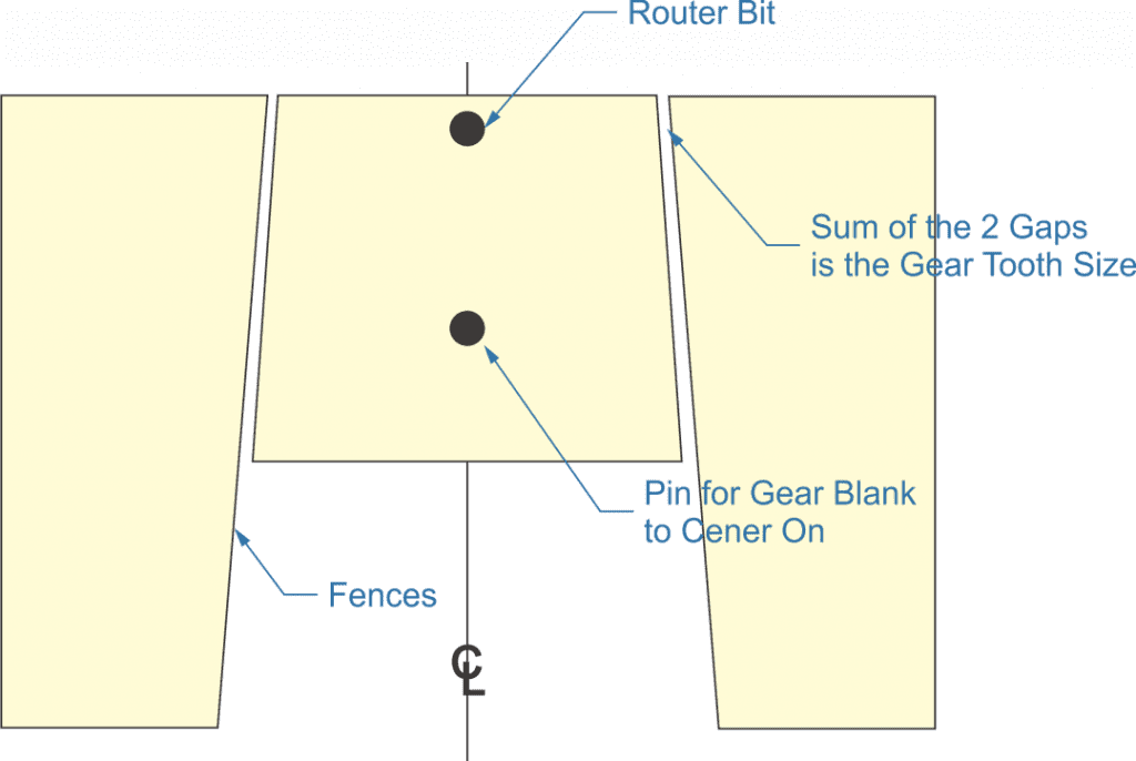
It is also possible to cut the teeth on a router table. In order to do so, it is necessary to make a simple sled for the gear blank to rid upon, and clamp two pieces of wood to the router table to act as fences. The overall shape of this is trapezoidal, with the angle of the fences and the sides of the sled match the angle needed for the sides of the gear teeth. The sum of the space between the sled and the two fences controls the size of the teeth.
Router setup
To use this jig, once it is set up, the fence is slid along one of the fences to cut one side of the gap between teeth and then slid along the other fence to cut the other side of that gap. A block clamped to the back of the router table can be useful in ensuring that the router bit doesn’t cut too deep.
Related Posts:
How to Make a Wooden Ring by Admin February 12, 2022 DIY When the word “rings” is used, it can spark a lot of different thoughts in people’s minds; mostly because there are a lot of different…
How to Make a Wooden Sword by Admin July 26, 2023 DIY Making a wooden sword is satisfying and fun, leaving the building with a great conversation piece, crafting table, or decoration for your office or den.…
How to Make a Wooden Barrel by Admin August 3, 2023 DIY Amongst woodworking, the cooper's craft of making barrels stands unique. The ability to turn wood into a waterproof vessel, capable of holding water or other…