Building Wooden Gears — My No-Nonsense Notes from the Garage
If you’ve ever thought about building wooden gears for a clock, a jig, or just to see if you could, you’re in the right place. I didn’t read a book. I didn’t take a class. I just needed a gear, didn’t want to wait for shipping, and figured, “I’ll cut one out of plywood.” That’s how this all started.
That first wooden gear was awful. Ugly. Teeth too fat on one side, too thin on the other. But it turned. Barely. I kept at it, though, and now I’ve got gears running in a sled jig, a sculpture, and even a crank handle setup I slapped together one weekend.
This isn’t some fancy how-to. It’s just what worked for me after messing up plenty. If you’re serious about learning how to build wooden gears that actually work, I’ll show you exactly how I do it—without overcomplicating the process.
Best Materials for Wooden Gears (And What I Regret)
You don’t need a high-end workshop to make wooden gears. But you do need the right materials:
Birch ply — no voids. Clean layers. Cheap plywood just splits and falls apart at the teeth.
Scroll saw — or a band saw with a fine blade. You need control, especially around tight turns.
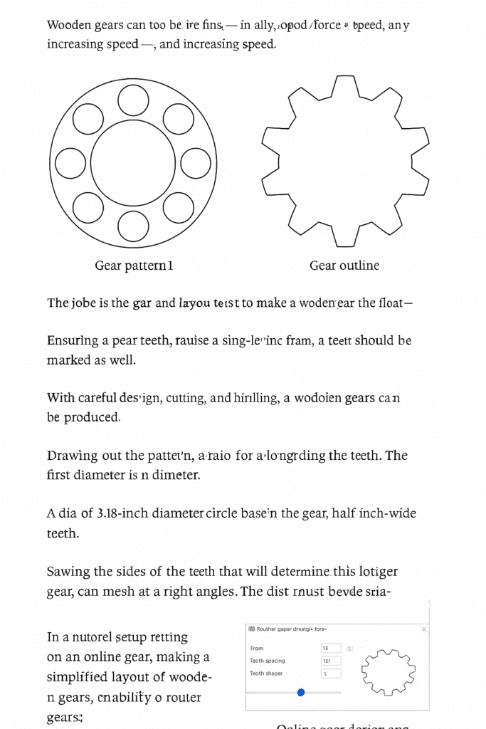
Printed wooden gear pattern — I use WoodGears.ca. It’s free, simple, and works every time.
Glue stick — avoids the mess of spray adhesive.
Files, clamps, dowels, and sandpaper — gear-making staples.
If I could go back, I wouldn’t waste a single sheet of softwood ply. I tried. The teeth ripped right off mid-spin.
Making My First Wooden Gear: What I Did Right (And Wrong)
I printed a 17-tooth wooden gear, glued it to a scrap piece of birch ply, and cut it out on my scroll saw. It looked solid at first glance. I was proud—until I spun it.
Turns out I forgot to drill the center hole first. That made alignment a nightmare. Also, I didn’t sand the teeth. Rookie move. When I paired it with another gear, it locked up.
After I sanded the tips, filed the valleys a bit, and rubbed on some wax, it worked. That moment when it spun clean? Felt like a win. That’s when I knew I’d make more.
Lessons I Keep Repeating When Making Wooden Gears
After making a couple dozen gears, I’ve developed some simple rules:
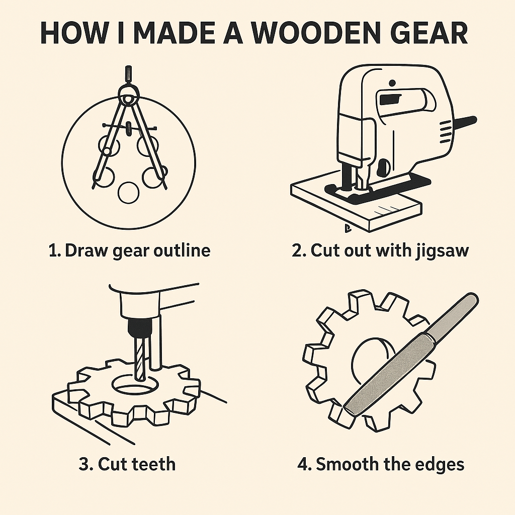
1. Cut the blank. Drill the hole first. Sounds basic. But I’ve skipped it more times than I care to admit.
2. Don’t rush the teeth. Go slow. Use a fine blade. Then file and sand. Perfect teeth = smooth meshing.
3. Mount it. Spin it. Adjust it. Test before calling it done. I use a simple dowel rig with a second gear to check for skips.
4. Finish matters. Paste wax is your friend. I’ve also used tung oil and poly, but wax feels smoother in motion.
5. Gear spacing is everything. Too tight? It’ll bind. Too far? It’ll skip. That’s where real testing comes in.
My Go-To Tools for Wooden Gears
If you’re serious about cutting wooden gears, these are the tools that saved me time and headaches:
Paste Wax — I apply this to every gear before final testing.
These might seem small, but they make a huge difference when you’re shaping wood into something that needs to move smoothly.
Wooden Gears FAQ (Based on What I’m Asked Most)
“Can I use plywood to make wooden gears?” Absolutely—but not the cheap kind. Birch or maple ply holds up. Avoid softwood panels.
“How long do wooden gears last?” Mine have lasted years. They’re in jigs and decor pieces that get moderate use. Waxing helps a lot.
“What size teeth should I use?” I usually go with ½” wide teeth. Too small and they break. Too big and they don’t mesh well.
“How do I figure out the gear ratio?” Divide the number of teeth. A 30-tooth driving a 10-tooth = 3:1.
“Why bother building wooden gears when I can buy plastic?” Because building wooden gears is part of the fun. Also, you can size them exactly how you want and customize them for your project.
“What about laser cutting?” Sure, if you have the gear (pun intended). But I enjoy cutting mine by hand. It feels more rewarding.
Common Uses for Wooden Gears
Wooden gears aren’t just a novelty. Here’s where I’ve used them:
In shop jigs: Like a gear-powered sled fence.
In kinetic art: Rotating sculpture bases, moving parts.
In home decor: Wall clocks, gear-themed furniture.
In kid projects: Crank toys and simple gear trains.
They’re also great for understanding mechanics—way better than looking at diagrams.
Pro Tips to Level Up Your Gear Builds
Test with paper first: I sometimes cut paper templates and test-spin them flat before using wood.
Use a dry-fit rig: Dowels, scrap wood, and clamps can become a test rig to dial in spacing.
Combine with pulleys: I once added a wooden pulley and gear system for a movable table clamp—it worked way better than I expected.
Try layering: You can laminate thinner plywood for a thicker gear. Looks cool, too.
Final Thought on Building Wooden Gears
If you’re sitting there wondering if you can pull this off—yeah, you can. Try it. Use scrap wood. Mess it up. Learn something.
When that first wooden gear spins clean, you’ll get hooked. I did. And now, I’m always finding new ways to add gears to my builds.
Wooden gears are more than decoration. They move things—and once you learn how to make them, so will you.
Related Posts:
How to Make a Wooden Sword by Admin July 14, 2025 DIY 1. Why I Still Make Wooden Swords I wasn’t planning to make a wooden sword that day. I just needed something—anything—for my kid’s last-minute costume.…
How to Make the Perfect Wooden Name Plate by Admin April 25, 2025 DIY Name plates are more than just labels — they’re subtle symbols of professionalism, pride, and identity. Whether it’s hanging outside an office door or sitting…
How to Make a Wooden Barrel by Admin April 23, 2025 DIY Wooden barrels are a timeless blend of functionality and craftsmanship. From aging fine wine to storing whiskey, these coopered containers are built not just to…